|
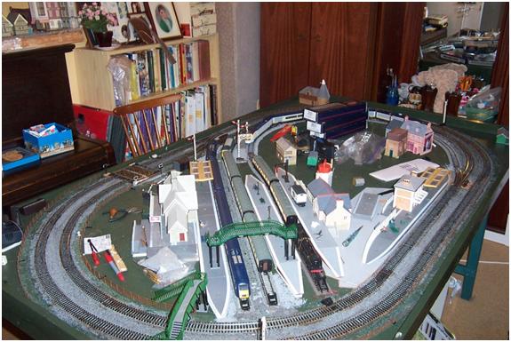
Old Castle Junction |
“Old Castle Junction” is an 8’x4′ layout comprising an oval of two tracks and three sidings which has been designed for DC and DCC operation.
Apologies for the fact that the formatting in this blog is a bit strange – I have had some technical issues with Vista!
Here is short video of the layout in action
DCC Electrification Notes
The layout comprises an oval of two tracks, the Outer Track, and the Inner Track.
-
The Outer Track is wired for DCC or DC operation and has a power track for live steam as well.
-
The Inner Track and the sidings have been wired for DCC operation only.
The Inner Track
Inside the Inner Track, there are three reception roads with four platforms for DCC operation only. There are Four sockets for phono plugs
Changes to electrical connections are made using phono plugs. DC or DCC operation can be selected by changing the phono connectors.
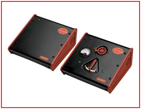
How to use the Phono Sockets
The four phono sockets are marked “Outer TRK”, “Inner TRK”, “12 volt DC”, and “16 volt AC
The 16 volt Ac for the points is supplied from a Hornby 16 volt 800 ma adaptor.
DCC operation is provided by a Bachmann Dynamis 2.3 amp 16 volt AC supply.
Points are switched using the Dynamis handset. The turnout motors are controlled via an EZ Command Dynamis Point Decoder 36-561.
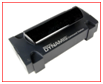
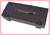
Power is fed to the layout via a terminal block under the baseboard.
Terminal point 1 is 12 volt DC controlled.
Terminal point 2 is 16 volt AC.
Rolling Stock
The “4 CEP” class 411 Southern Electrical Mulitiple Unit is fitted with an EZ command 21 pin decoder 32-554. This decoder has 12 volt DC operational capability which can be turned off by setting a CV. (Configuration Variable). 12 volt operation is on by default, so this means the train can operate either by DCC or DCC. Operation under DC can be erratic if the track is not clean.
Class 33 is fitted with R8245 Hornby Sapphire Decoder. This is a 1.5 amp decoder which can be programmed to carry out a sequence of train movements, start accelerate, slow down, stop reverse.
All the other locos and units have Hornby R8249 1amp decoders.
The Pendolino and the Class 43 GNER have two decoders, one for the power car, and one for the trailer car. The Eurostar only needs one decoder.
- Note the Bachmann 36-552 decoder has no facility for DC operation. So do not order any decoders of this type for a DC/DCC layout!
All locos and units on Old Castle Junction have DC capability, so can be stood on DC controlled track.
Old DC locos and units which have not been converted to DCC should not be placed on track which is connected to a DCC controller.
The Dynamis Controller.
The Dynamis Wireless DCC Digital Control System has its own power supply. Point motors can be operated using power taken directly from the Dynamis power supply, but this has not been done on Old Castle Junction: A separate PSU is used to power point motors.
Bachmann 36-561 EZ Command Dynamis point decoder
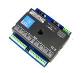
Point motors are operated via the Bachman E-Z Command Dynamis Accessor Decoder User Guide. The output mode selector switch is set to “K83” operation for solenoids (the default setting)
I have to report a failure with this Unit. It worked until the Warranty period had expired!
Electrically Operated Points
The EZ Command point decoder which has four outputs costs £30. Four PECO passing contact switches PL26 cost £4.50 each and the housing PL27 costs £3. This works out to £21.
36-507 Bachmann EZ Command Dynamis Handset

This handset is fitted with 4 rechargeable AAA batteries.
All the locos and units which have been converted to DCC have been entered into the locomotive roster.
The Dynamis handset does not tell you whether or not a specific loco is present on the layout. If the loco has lights, you can determine that the loco is ready by turning the lights on. If the loco has no lights, then the only way to know if it is present is to run it.
The fact that a loco is in the loco roster does not mean it is on the layout.
Main Track and Service Track
The Dynamis Handset has a facility to make a distinction between a “Main Track” and a “Service Track”.
But
The facility to use the Main Track only exists if you have a “Bachmann 36-508 EZ Command Dynamis Pro Box:
Without the Pro Box, You can only programme CV values using the Service Track. (If you select Main Track, when you have not got a Pro Box, it does not do anything).
The main part of the layout may be used as a Service Track, if all other locos are removed. The facility to use the main layout as a Service Track is useful if you want to programme two decoders to the same address. For example in the case of the Pendolino you need to programme both the power car and the trailer car to the same address. The entire Pendolino is too long to fit on a separate service track, so the ability to use a track on the main layout as a service track comes in handy….
On this layout, the Outer Track can be designated as a Service Track. There would normally only be one train on this track anyway, since it has no sidings. The cross-over to the Inner Track has insulated fishplates, so once the Inner Track has been disconnected by unplugging the phono plug which connects it to the DCC system, the outer track can then be used as a service track without having to remove all other locos from the layout.
The Sapphire Decoder
The Hornby Model Railways R8245 Sapphire digital loco decoder 1A current with 1.5A stall has Auto Control which allows loco to run on internal time functions without input from the controller.
The Auto Control Cycle (ACC) set up is controlled by the status of CV140. How to use this is described in a separate document entitiled “Sapphire Decoder”.If you do not have this, see the Ontracks website. Currently:
http://www.ontracks.co.uk/index.php?page=fromLibrary&guide=155
Since none of the other locos on Old Castle Junction currently has a Sapphire Decoder, the Class 33 loco which is fitted with it can be reprogrammed on the Service Track on any part of the layout without affecting the other locos. However, it is advisable to move the train to the outer track for reprogramming since any mistake would affect all locos on the layout.
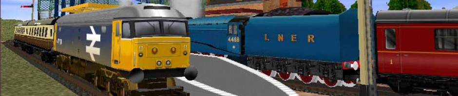
Live Steam
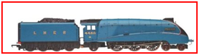
The live steam Mallard loco pictured above can only be run on a track set aside specially for the purpose. The output from the live steam controller has to be connected to the track via the R8206 power track supplied.
http://www.hornby.com/live-steam-157/r8206/product.html
Observe correct polarity
Note the flex from the controller to the power track has to be connected with the white line on the left. If you connect it the wrong way round the controller cuts out with a high pitched whine!
Oil
Only add a small amount of oil. If you overdo it, you get oil spashes all over the layout.
Red and Green Lights
The user guide tells you to leave the locomotive with the throttle in the “red” position. But if you do this, it is difficult to get the locomotive started. If you leave the locomotive in the “green” position, then it will start running as soon as pressure is up.
When the loco is left in the Red position the wheels lock, and you cannot wheel it onto the track using the chute.
The live steam engine makes the track black, and you have to clean it before the layout can be used for DC/DCC operations. The loco runs for about half an hour on a full tank of distilled water.
No other locos, DC or DCC can be on the same track or electrical section has a live steam loco. If this precaution is not observed, any loco that receives power from the live steam transformer will shoot forwards. The live steam loco must also be removed from the layout before any DC or DCC operations.
Tuesday, 25 September 2012
